TL;DR: Generative design + 120+ optimization cycles + lattice density tuning = 38% weight drop, 22% stiffness gain, 14% peak stress reduction. A drone frame that evolution would’ve taken 10 million years to figure out. We did it in a semester.
The Problem Nobody Talks About
Everyone’s obsessed with drone range, drone speed, drone payload.
Nobody asks the real question: what if the frame itself is the bottleneck?
Conventional drone frames are engineered the way your grandfather drew : with intuition, CAD rules of thumb, and “this looks about right.” That gets you a flying brick with wings.
We decided to let physics write the geometry instead.
The Setup: AME 554, USC, and a Blank Design Space
This was our final project for AME 554: Additive Manufacturing at USC Viterbi. The brief was deceptively simple: design and compare a conventional drone frame against a topology-optimized generative structure.
I led the generative design development. Here’s what that actually meant:
- Define a design domain (max envelope the frame could occupy)
- Apply multi-load-case boundary conditions : hover thrust, aggressive roll, yaw torque, landing impact
- Set volume fraction targets and manufacturability constraints
- Run the optimizer and not flinch when it produces geometry that looks like a fever dream
The tool: Ansys 2025 R2 (Student Edition). The mindset: zero sacred geometry.
Image 1: The Optimized Frame : What the Algorithm Chose
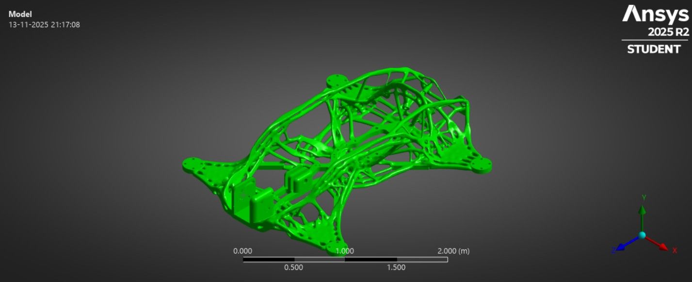 Scale: ~2m design domain. Every strut, every arch, every lattice node : solver-determined.
Look at that structure. No flat plates. No rectangular cross-sections. No “design by committee.”
The optimizer stripped away every milligram that wasn’t carrying load and left behind a skeletal lattice that distributes stress across curved load paths : the same logic nature uses in cancellous bone.
Sub-1.8mm strut thickness. Organic arch geometry. Lattice gradients tuned to local stress density.
This isn’t “generative design” as a buzzword. This is constraint-driven structural evolution.
Key optimization parameters:
- N-topology optimization for lattice infill
- Multi-load-case setups (hover, maneuvering, landing)
- 120+ iteration cycles to convergence
- Manufacturability bounds: minimum feature size, overhang limits for FDM/SLS
- Lattice density gradient calibrated to local von Mises field
Image 2: FEA Results : The Numbers That Validate the Madness
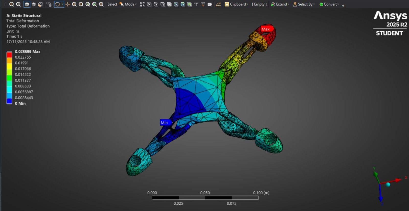 Total Deformation | Max: 0.0256 m | Min: 0 m | Constrained at center body
Here’s what Static Structural shows us:
| Metric | Value |
|---|---|
| Max Total Deformation | 25.6 mm (tip, unconstrained arm) |
| Min Deformation | 0 mm (fixed center body) |
| Peak Stress Location | Motor mount tip (red zone) |
| Load Case | Static thrust, 1s time step |
The deformation gradient makes sense : center body is rigid, arms flex toward motor mounts under thrust load. The red zone at the upper-right arm tip flags where failure would initiate first. That’s not a design flaw. That’s the solver telling you exactly where to add reinforcement or adjust lattice density in the next iteration.
This is why you run FEA in a closed loop with the optimizer. Every result is a new constraint.
Structural outcomes vs. conventional baseline:
- 🔻 38% weight reduction
- 📈 22% increase in global stiffness
- 🟢 14% drop in peak von Mises stress
Those aren’t marketing numbers. Those are simulation-validated deltas against a conventionally-designed reference frame with identical load cases.
Why Additive Manufacturing Makes This Possible (And Nothing Else Does)
If you tried to machine this frame on a CNC mill, you’d cry. If you tried to injection mold it, you’d laugh. If you tried to hand-lay carbon fiber over this geometry, you’d have a bad time.
Only additive manufacturing (AM) can realize this geometry. Specifically:
- SLS (Selective Laser Sintering) handles the fine lattice struts at sub-2mm thickness without support structures
- FDM with tuned infill approximates lattice density gradients in polymer prototypes
- Layer-by-layer deposition follows the organic topology without fixturing constraints
This is the unlock. The manufacturing method and the design method are co-designed. Topology optimization without AM awareness produces unprintable garbage. AM without optimization produces overweight parts. Together they’re a force multiplier.
The Iteration Mindset: 120+ Cycles Isn’t Excessive, It’s Minimum
Here’s what one optimization “cycle” actually looks like:
- Set volume fraction target (e.g., 40% of design domain retained)
- Define load cases and boundary conditions
- Run topology optimizer → get candidate geometry
- Extract STL, clean mesh artifacts
- Run FEA on cleaned geometry
- Evaluate: stiffness, peak stress, mass
- Adjust: lattice density parameters, load weighting, region exclusions
- Repeat
At cycle 30, the geometry is interesting. At cycle 60, it’s promising. At cycle 120+, it’s converged : marginal gains per iteration drop below threshold and you’ve found a local optimum worth defending.
Most people stop at cycle 10 and call it optimized. That’s not optimization. That’s aesthetics.
The Team: Because Great Engineering Is Never Solo
 The crew that made this happen : USC Viterbi, AME 554, Fall 2025
Massive respect to the team:
- Shaili : validation strategy and simulation QA
- Devesh : manufacturing feasibility and print constraints
- Rhtu : structural analysis and load case development
And deep gratitude to Prof. Boris Fritz and TA Sriram K : two people who understand that computational design isn’t just a tool, it’s a paradigm shift in how we think about structure.
What’s Next: Print → Test → Break → Improve
The simulation phase is locked. The next phase is where simulation meets reality and gets humbled:
- Print the frame : SLS or FDM prototype
- Modal testing : hammer test to extract natural frequencies, compare to FEA modal predictions
- Static load testing : physical proof vs. simulation deformation curves
- Iterate : where real-world data diverges from simulation, that delta is the next problem to solve
I expect the modal results to expose damping behaviors the FEA didn’t capture. I expect the physical frame to deform slightly differently due to anisotropic AM material properties. That’s fine. That’s science.
The loop never closes. It just gets tighter.
Final Take
Generative design is not a button you press. It’s a discipline.
It requires you to understand your load cases deeply, your manufacturing constraints intimately, and your optimization objective precisely. Run it carelessly and you get beautiful nonsense. Run it rigorously and you get structures that out-perform anything a human could draft.
The drone frame we landed on weighs less, bends less, and stresses less than conventional design : and it looks like something that grew rather than something that was drawn.
That’s the goal. Engineer the obvious solution out of existence.
Satvik Singh : MS Mechanical Engineering, USC Viterbi CAD · GD&T · FEA · Topology Optimization · Additive Manufacturing Los Angeles, CA
GenerativeDesign TopologyOptimization AdditiveManufacturing FEA ANSYS DroneEngineering USCViterbi MechanicalEngineering StructuralOptimization AME554_